 Hey There!
The third pillar of the CQE Body of Knowledge is dedicated to the design of products & processes and it contains 7 main chapters within it:
- Classification of Quality Characteristics
- Design Inputs & Reviews
- Technical Drawings & Specifications
- Design Verification & Validation
- Process Validation
- Reliability & Maintainability
- Quality Risk Management Tools
In terms of the overall body of knowledge, this pillar comprises 23 questions out of the total 160 which is almost 15% of the exam.
Classification of Quality Characteristics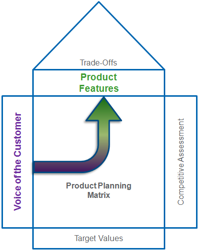
The Product & Process Design pillar of the CQE Body of Knowledge is the critical first step in delivering a high quality product.
Delivering a high quality product starts with capturing your customers needs and then translating those needs into Products Features, which are also known as Quality Characteristics.
The most important take away from this chapter is the fact that all product features (quality characteristics) are not created equal.
As you move through the design process, you’ll want to focus your attention on the critical features that result in the satisfaction of your customers.
This is accomplished through the classification of quality characteristics.
This process takes advantage of the Pareto Principle, which tells us that 80% of your customers satisfaction will be delivered through 20% of your products features.
By going through this process, you will identify those product characteristics that ensure the Safety, Quality, Performance, Functionality & Reliability of your product.
And as a result, you will have established a hierarchy of importance for the various characteristics of the products that will guide the later stages of product development.
Design Inputs & Reviews
This chapter covers the 3 initial steps of the new product development process that are critical to your so organizations success as a business.
The first is to identify all of your different customers who will be sources of design inputs, and then effectively capturing your customers wants/needs & expectations too guide your design.
The next major step is the process of transform your customers needs (design inputs) into an epic design concept using tools like Robust Design, Quality Function Deployment (QFD), Design for X (DFX), Design for Six Sigma (DFSS) & Quality by Design.
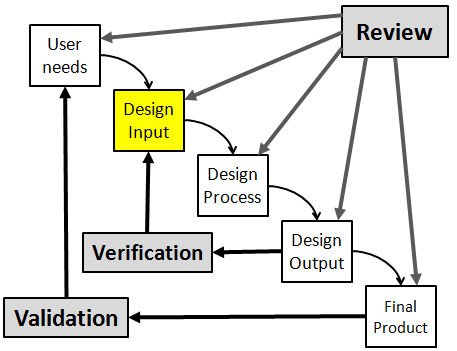
Finally, you must utilize the design review process periodically to confirm that your design efforts are still on track to deliver an epic product.
When you’ve completed these three steps, you’ve done a lot of the heavy lifting that’s required for developing a new product. As you move through those design methodologies, you’ll also likely be required to create your detailed design output documents.
Your detailed design outputs include your the engineering drawings, product specifications & requirements, labeling requirements, bill of material, inspection criteria, and assembly procedures that describe your final product.
These outputs should be created in such a way that they clearly describe all of the components, assemblies & sub-assemblies of your product.
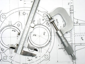
One of the critical aspects of Design Output is the creation of your engineering drawings which are both a communication tool and a control tool to ensure that your product is manufactured & inspected consistently throughout its lifecycle.
This topic is covered next in the next section, Technical Drawings & Specifications.
 Technical Drawings & Specifications
In the last chapter (Design Inputs & Reviews), we covered the three phases of product design, which often result in the creation of detailed engineering drawings associated with your new product.
These Engineering or Technical Drawings serve a number of different purposes.
One of the most important is to capture the intention of the designer and all of the requirements associated with the newly designed product. The next benefit or purpose of the engineering drawing is to act as a communication tool.
As a Quality Engineer you’re likely aware that there are many different people within the manufacturing process who will need information about the new components or assemblies that have been designed.
This includes process designers, component buyers, component suppliers, raw material inspectors, assemblers, post-assembly QC inspectors & lastly the customers themselves.
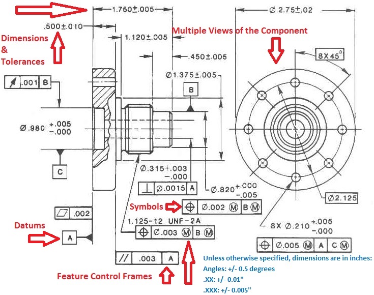
GD&T (Geometric Dimensioning & Tolerancing) Explained
There are 7 aspects of the GD&T methodology that we will discuss, these include: Views, Dimensions, Tolerances, Symbols, Datum’s, Feature Control Frames & Title Blocks.
Design Verification & Validation (V&V)
Once a design has been finalized, it’s now up to the design team to prove that their design actually meets the needs & intended use of the customer – which is the ultimate goal of designing a new product.
This is achieved through Design Verification & Validation.
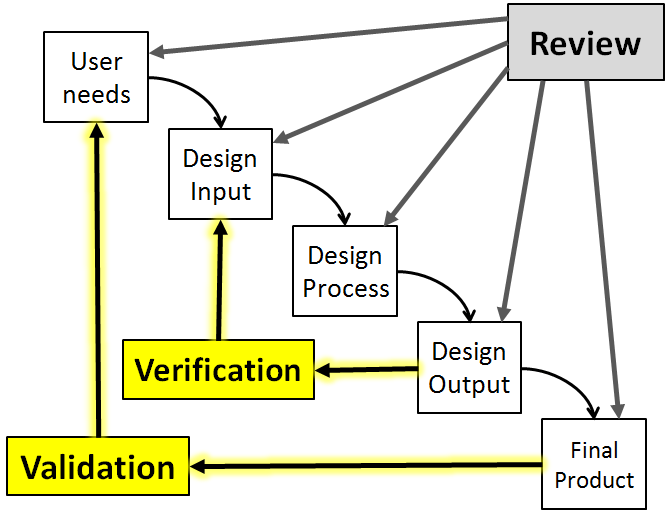
This chapter will introduce the concept of Design Verification & Validation along with the key definitions, standards, processes, deliverables & best practices associated with this important Design Activity.
We start by covering the difference between Design Validation & Design Verification and then quickly discuss a handful of the Quality Standards that provide guidance for Design Validation.
From there we move into the nuts and bolts of executing a Design Validation with some of generally accepted best practices surrounding the Design V&V Process.
Next, we touch two of the common Statistical Tools that you can utilize during Design Validation. Finally we discuss the relationship between Design V&V and Process Validation.
Process Validation
The next stage in product development is Process Validation, because once you’ve determined that you’re new products design will meet your customers needs & intended use, you’ll now need to design a process that can consistently produce that product.
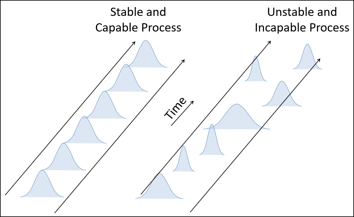
We start this chapter with the definition of process validation and what that means to the overall process & approach. Included in that conversation are the benefits of process validation, which is really the WHY of the entire process.
We follow that up with the key difference between Validation & Verification as it relates to your process. This distinction has been a hotly debated topic that requires discussion.
From there we do a quick review of the existing Quality Standards governing Process Validation that are in play today.
Next is the meat and potatoes of Process Validation – by this I mean a walkthrough of the 3 different types of validation and the 3 stages of Process Validation including Process Design, Process Validation & Process Control & Monitoring.
Within these 3 stages we cover the Equipment Qualification Process (IQ, OQ, PQ) as well the relationship between Process Validation and Risk Management and then move to some of the validation best practices (Checklists, Protocols & Reports).
We wrap everything up by covering the 3rd stage of Process Validation which is Process Control & Monitoring & the Statistical Methods used in Validation.
As shown above, the ultimate goal of Process Validation is to confirm that your process is both stable & capable, which will ensure that it is able to consistently produce good product.
Reliability & Maintainability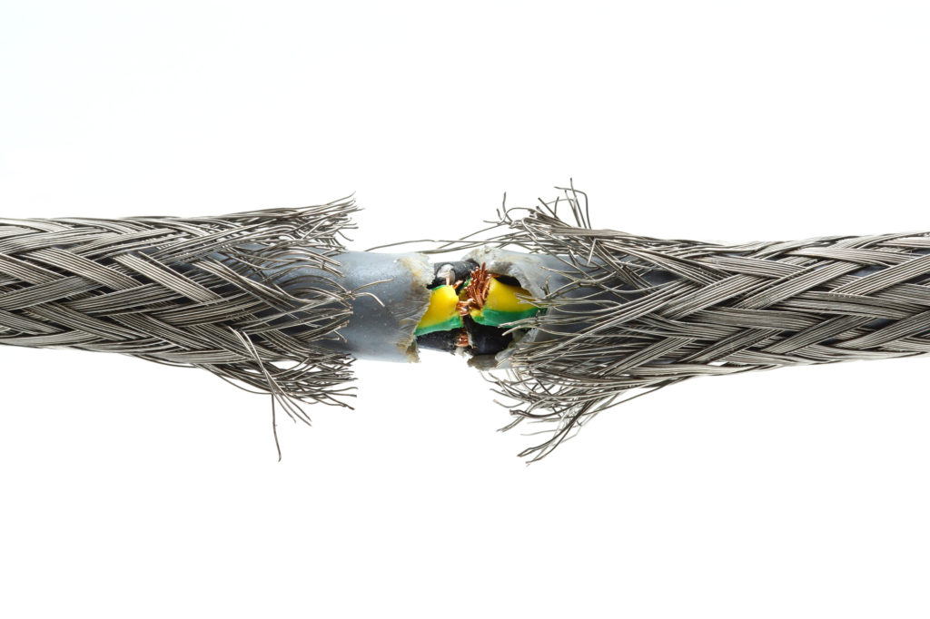
This chapter includes the 4 key tools & techniques associated with Reliability that will assist you in improving your products design and increasing its reliability and maintainability.
The first topic of discussion is the basic concept of a Reliability Function which include:
- PDF’s (Probability Density Functions),
- CDF’s (Cumulative Distribution Functions),
- Reliability Functions
The 2nd topic introduces the primary Distribution Models that can be used to estimating or predicting reliability which include:
- the bathtub curve
- the weibull distribution
- the exponential distribution
The 3rd topic covers the common reliability and maintainability indices used within Reliability Engineering to describe a product or process:
- Failure Rate
- Mean Time To Failure (MTTF)
- Mean Time Between Failure (MTBF)
- Mean Time To Repair (MTTR)
- Availability
The 4th & final topic is the concept of System Reliability Analysis for Series & Parallel systems.
This is the last and final section because it allows you to bring everything together and calculate the entire reliability of your system or process by taking into considering all of the sub-systems within your system or process that can fail.
Quality Risk Management Tools
The last chapter in the Product & Process Design section is all about Risk Management, which begins during design & development.
In fact the safety & reliability of your product are designed into your product in the same way that quality is.
In the overall risk management process there are a few tools that are instrumental in identifying, assessing, controlling & ultimately managing risk.
These tools include the FMEA (Failure Mode Effects Analysis), the FMECA (Failure Mode Effects Criticality Analysis) and the FTA (Fault Tree Analysis).
These tools can be used during the product & process design phase to improve Reliability/Quality & Safety of your product.
This improvement is achieved through the identification, assessment & correction of potential issues that might introduce risk to your customer in terms of safety or reliability.
In this section we will define each of the 3 risk management tool (FMEA, FMECA & FTA) with a description of how each is constructed and a discussion of how to interpret each in order to improve your product/process:
We also discuss how these Risk Management Tools fit within the entire Risk Management process. For example, the FMEA process captures the steps of Risk Identification, Risk Analysis & Risk Assessment all in one.
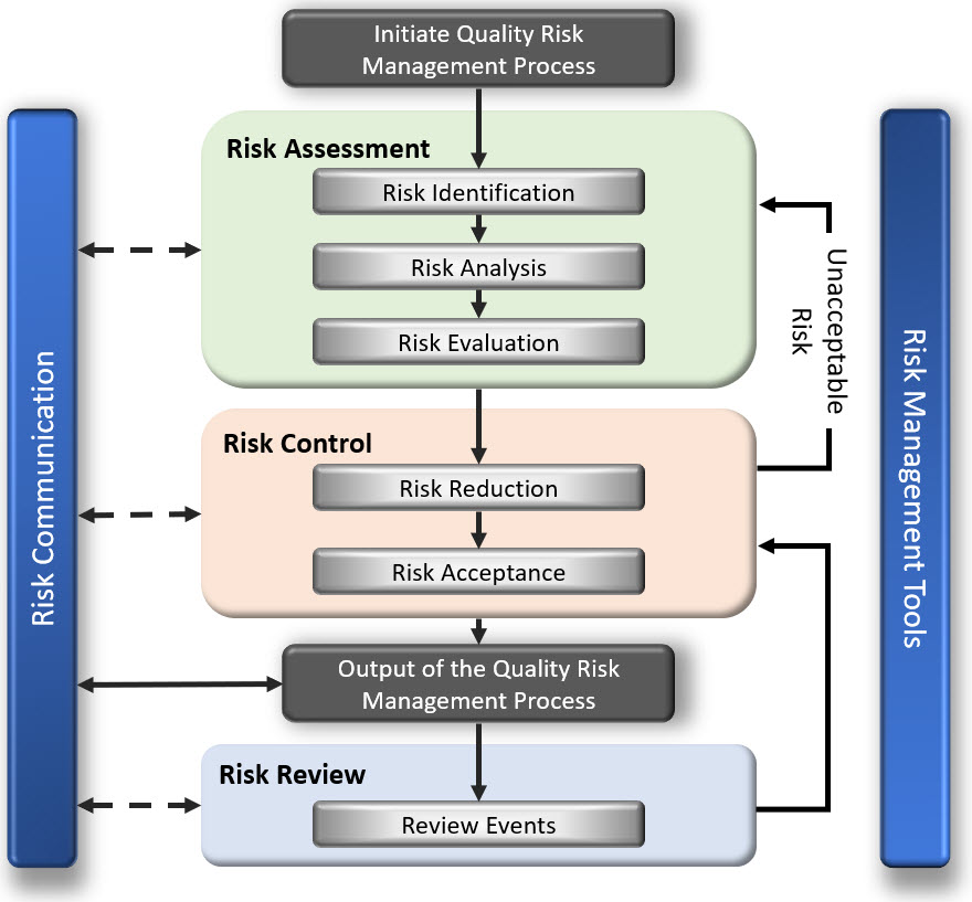
Ready to see the next Major Pillars: Management & Leadership, the Quality System, Product & Process Control, Continuous Improvement